
Getting the best out of your borehole pump : A real-world case
/by John Tonkin
One of the barges used by SpaceX to land the first stage of their boosters on (far out in the ocean would you believe!) is called Just Read The Instructions. I guess this name comes from the distinct possibility that we all are guilty of “If at first you do not succeed, read the instructions”. The cost of failure varies in direct proportion to the capital cost AND the thickness of the instruction manual and this is one such story. Bear with me as it has a happy ending.
Here's a diagram of the installation:
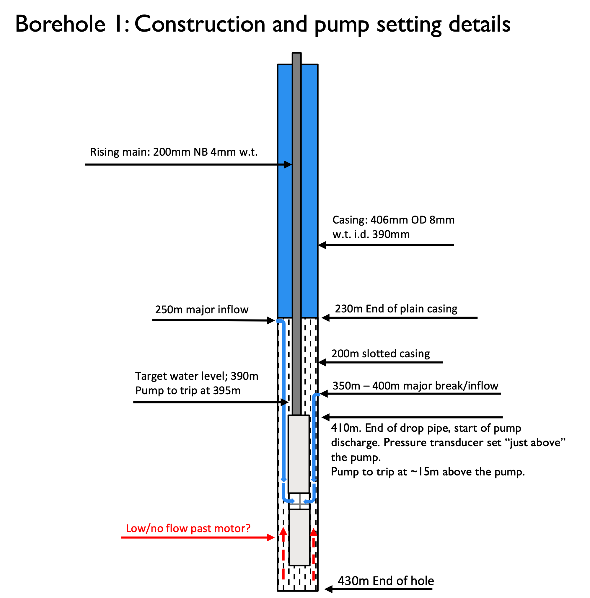
Figure 1: Details of the pump setting and borehole construction
The request for quotation asked for a flow rate of 300m3/hr against a Total Dynamic Head (TDH) of 420m. This elicited a supplier proposal for a 285mm OD 400kW 15-stage stainless steel borehole pump. Controlling the pump was a 550V Variable Speed Drive (VSD) through a Programmable Logic Controller, which had the capability of logging many of the operating parameters of the system. Initially the logging frequency was set for 2 minutes but this was increased to 2 seconds to meet the need for more detailed analysis of sub-standard performance. While this had the disadvantage of creating a Mb size data file, it had the desired effect of allowing short duration but substantial departures from normal operation to be identified and analysed in fine detail.
Orders were placed and the pump installed. During the commissioning procedure, the first inkling of the pump being too big for the application became apparent. Initial capacity delivered was close enough to the design capacity but this was achieved at initial (high) water levels. As the level dropped, so did the flow rate from the pump. At the required dynamic level,~15m above the pump, the flow had declined to half the design figure. Power absorbed at this level was ~150kW. This was an altogether different pump that was needed. As the installation could see high flows after rain fall or other forms of recharge, it was decided to keep the installation as it was, using the VSD as much as possible to accommodate, what had come to be recognised as a pump that was substantially oversized.
The first few months of operation were interspersed with some stoppages of relatively minor proportions. These were, nevertheless, the cause of some significant expenses. The period ended with a breakdown which required the removal of the pump. Due to flooding, (this is a mine dewatering application) there was an urgent requirement to get the pump reinstalled and running again. This was done after a basic investigation into the incident was conducted. The Non-Return Valve (NRV) fitted to the pump discharge was replaced and two high pressure, surge resistant valves were installed ~ 1m above the pump.
All seemed good for a few more months before the pump had to be removed for a second time. Despite a more detailed analysis being conducted, no conclusion was reached as to the root cause of failure. The opportunity was taken to replace the pump/motor unit with a lower capacity pump fitted with a 300kW motor and the data logging cycle was shortened to 2 seconds. The smaller pump seemed to make a positive contribution to stability of the installation but unfortunately after a marginally longer period of time, this new unit had to be removed.
At this point it was decided to assemble a team of experts drawn from the pumps, pipes, IT, and electrical fraternities and conduct an exhaustive analysis of the very large data file that had been created over the period of operation. This revealed an unsteady event that always occurred when the VSD changed over from the drawdown phase (static level to target dynamic level) to the level maintenance phase.
It was established that these two incidents of instability caused conditions in the motor windings that significantly exceeded the manufacturer’s maximum operating parameters. Tear-down of the 300kW motor and the second 400kW motor clearly supported root cause hypothesis put forward from the data shown in Figure 2.

Figure 2 Two incidents of instability during change over from drawdown to level maintenance
The installation of the next pump/motor unit was carried out using an available 300kW motor with a pump end that, although is marginally bigger that required, it will still have an adequate reserve in case of future increases in inflow into the mine. In addition the VSD can be ramped up beyond 50Hz to add capacity.
In collaboration with mine management, it was decided to amend the operating regime to one whereby the water level is drawn down to the trip point (15m above the pump) and the pump is switched off. The water level recovers within 30 minutes to the original (static) level and, based on a specific pre-set time, the pump starts up and repeats the cycle.
It must be pointed out that a significant challenge was encountered due to the interaction between a centrifugal type pump and a VSD. In these pumps, the TDH delivered varies, broadly speaking as the square of the speed. As the water level dropped in the borehole, there was a need to increase the pump speed (Hz) but this brought about an increase in the flow rate that is ~directly proportional to the pumps speed. This occurred at the worst possible time as the lower level in the borehole meant a lower delivery requirement for the pump, not an increase in flow. The work around was to allow the flow rate to decrease to a set value (30m3/hr) and then use the PLC to command the VSD to increase the pump speed by only 1 Hz! This increased the head and capacity until the level decreased further and the capacity moved back down to 30m3/hr, at which point the pump speed was increased a further 1Hz.
Our final speed range started at 40Hz (top static level) then increased in steps of 1Hz every time the flow rate reached 30m3/hr. The final pump speed topped out at 46 Hz which leaves considerable margin for future accommodation of any higher flooding conditions.

Figure 3 Data showing relationship between pump speed and flow rates during drawdown
The data shown in Figure 3 shows how the problem of matching pump speed to capacity delivered and Total Dynamic Head required is accommodated.
Finally, a graphical representation of the current operating cycle is shown in Figure 4

Figure 4 Current operating cycle
Maximum flow occurs when the water level is at its highest in the borehole.
Conclusions
A number of points stemming from this case study need to be emphasised:
1. The true sustained yield of any borehole MUST be established with a fair amount of accuracy. This can only be done by following an accepted yield test procedure. The services of a reputable yield testing contractor and hydrogeologist should be retained for these services for high value projects such as this one.
2. While having reliable borehole yield data is very important, cognisance must be taken of the fact that these data are a “snapshot” pertaining to the CURRENT conditions in the borehole. Rainfall patterns and the influence of other boreholes intersecting the same aquifer will have a material effect on the potential yield of the borehole.
3. Commissioning of any new pump installation is essential. Analysis of the gathered data will give a clear idea of how close the design process is to the reality of what the borehole is able to deliver on a sustained basis.
4. A thorough and detailed analysis is essential if repeat failures are to be avoided. There is always an all-consuming urgency to get the system back into operation, but a small amount of time spent on establishing root cause of failure will substantially reduce costs.
5. Data collection is a necessity not a luxury. Good data available to a qualified technician is inestimably valuable. Perceptions, assumptions and inaccurate, inappropriate data will lead to incorrect conclusions and inappropriate remedial actions. Inevitably, these all lead to repeat breakdowns and unnecessary expense.
6. Data collection, analysis and corrective action are excellent learning tools that make substantial contributions to staff development, job satisfaction and, of course, drastic reductions in operating costs and increases in plant reliability.
Click here for more information or contact:
Chris Munnick +27 72 256 0926 chris@carl-hamm.co.za or
Jeanette van Wyk +27 83 488 0883 jeanette@carl-hamm.co.za
John Tonkin is the editor of the Journal and offers training and advisory services at John Tonkin and Associates. His areas of specialism include pumps, pipes and valves within the system as a whole.

